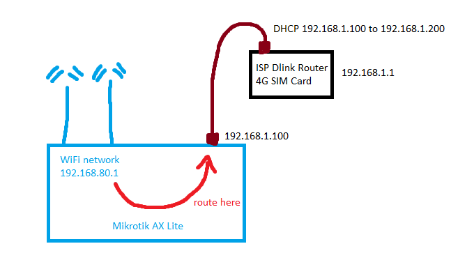
Here is what my setup looks like with a bridge
- My ISP provided me with a 4G router. It is a DLink Archer MR600.
- The DLink router IP address is 192.168.1.1
- I have my own personal Mikrotik AX Lite (L41G-2axD) running Router OS 7.10.1
- When I plug the DLink into my Mikrotik (ether1), my Mikrotik gets IP 192.168.1.100 from the DLink (I made it static on the DLink so it never changes).
- I then created a WiFi network on my Mikrotik and put both the WiFi network and ether1in the same bridge, and everything works as expected (WiFi work and all clients get IP addresses and can connect to the internet)
- This works because the Mikrotik bascially uses the DHCP from my DLink and just passes traffic back and forth.
I dont want to use a bridge anymore
But now I want a more advanced setup, so in other words I don’t want a bridge. I want to create a new WiFi interface on my Mikrotik, assign a DHCP server to it, and route all traffic from that WiFi network over my ether1 port which is connected to my DLink as in the picture above.
In a nutshell, we will:
- Create a new WiFi interface
- Mark connections and packets coming from that WiFi interface using mangle rules
- And then create a routing rule so that only those packets are routed over ether1
Below is my config (I removed any other config unnecessary to this tutorial)
Step 1 – WiFi interface
Lets create a new WiFi interface. Make sure to select your country, set an SSID, and set the appropriate security (e.g. WPA2/WPA3)
[admin@MikroTik] > interface/ print
Flags: R - RUNNING; S - SLAVE
Columns: NAME, TYPE, ACTUAL-MTU, L2MTU, MAX-L2MTU, MAC-ADDRESS
#    NAME                TYPE    ACTUAL-MTU  L2MTU  MAX-L2MTU
7 RS mikrotik-mtn24      wifi          1500
Step 2 – Address
The address ether1 is getting from the DLink is 192.168.1.100, so lets add it so that the Mikrotik knows about it. Make this static on your DLink so it never changes. We will come back to this again later to set the address for our new WiFi interface as well
[admin@MikroTik] > ip address/ print
Columns: ADDRESS, NETWORK, INTERFACE
# ADDRESS           NETWORK       INTERFACE
;;; defconf

1 192.168.1.100/24  192.168.1.0   ether1
Step 3 – DHCP
Now create an address pool, and a DHCP server, and dont forget that under DHCP server you need to add the network so that your DHCP server will give out a Gateway and DNS.
[admin@MikroTik] > ip/pool/ print
Columns: NAME, RANGES
#  NAME                 RANGES
1  mikrotik_mtn24_pool  192.168.70.150-192.168.70.210
[admin@MikroTik] >


[admin@MikroTik] > ip/dhcp-server/ print
Columns: NAME, INTERFACE, ADDRESS-POOL, LEASE-TIME
# NAME                 INTERFACE       ADDRESS-POOL         LEASE-TIME
1 mikrotik_mtn24_dhcp  mikrotik-mtn24  mikrotik_mtn24_pool  30m


[admin@MikroTik] > ip/dhcp-server/network/ print
Columns: ADDRESS, GATEWAY, DNS-SERVER
# ADDRESS          GATEWAY       DNS-SERVER
0 192.168.70.0/24  192.168.70.1  192.168.70.1
Step 4 – The routing table
Now lets create a new routing table as we will use packet marking to route traffic correctly. In Mikrotik 6 this is not necessary, because in your mangle route rule you can just type this in.
[admin@MikroTik] > routing/table/ print
Flags: D - dynamic; X - disabled, I - invalid; U - used
0 D name="main" fib
1 name="mikrotik_mtn24_route_table" fib
Step 5 – Firewall
Now lets create the mangle rules. Make sure your in-interface is your newly created WiFi interface.
In the mark-routing rule, make sure you select your newly created route table.
You will see in my NAT rule I am NAT’ing to a bridge, but in your case you will NAT to ether1 (I have some other things connected to my Mikrotik for which a bridge is fine)
[admin@MikroTik] > ip firewall/mangle/ print
Flags: X - disabled, I - invalid; D - dynamic
3    chain=prerouting action=mark-connection new-connection-mark=mikrotik_mtn24_conn passthrough=yes dst-address-type=!local in-interface=mikrotik-mtn24 log=no log-prefix=""
4    chain=prerouting action=mark-routing new-routing-mark=mikrotik_mtn24_route_table passthrough=no connection-mark=mikrotik_mtn24_conn in-interface=mikrotik-mtn24 log=no log-prefix=""


[admin@MikroTik] > ip/firewall/nat/ print
Flags: X - disabled, I - invalid; D - dynamic
0    chain=srcnat action=masquerade out-interface=bridge-mtn log=no log-prefix=""
Step 6 – Adding an Address for our WiFi Interface
Now lets go back to Address and add an address for our new WiFi Interface. Remember in a previous step we address the address to ether1 so long and we said we will come back here.
[admin@MikroTik] > ip/address/ print
Columns: ADDRESS, NETWORK, INTERFACE
# ADDRESS           NETWORK       INTERFACE

1 192.168.1.100/24  192.168.1.0   ether1
2 192.168.70.1/24   192.168.70.0  mikrotik-mtn24
Step 7 – The actual routing
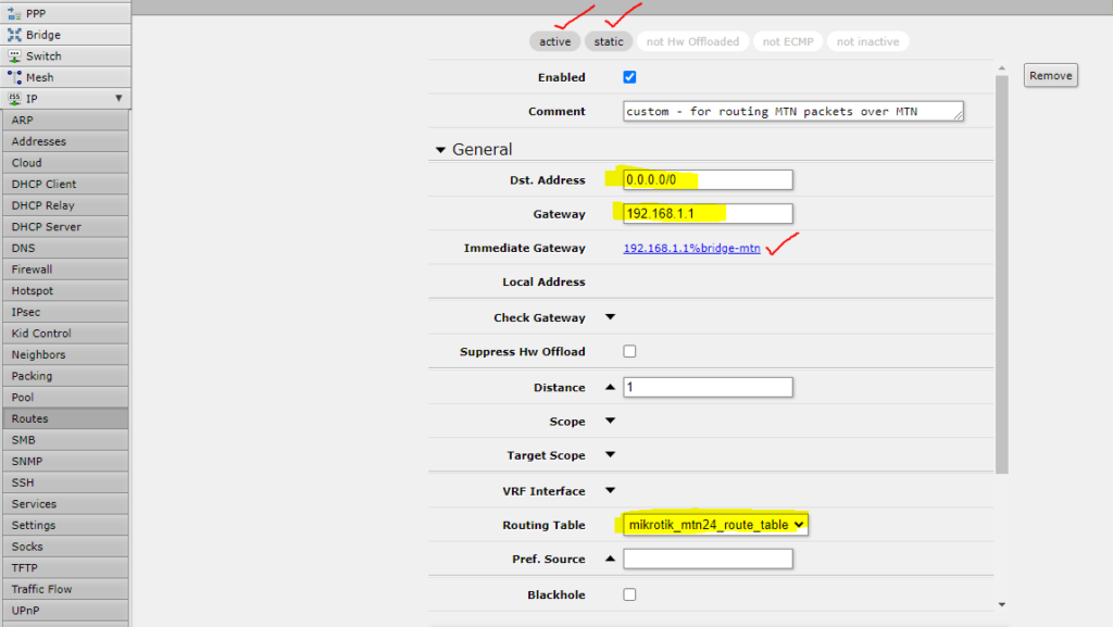
So after all this setup we can finally add the routing rules. We will add 2 static routes:
- 1 for our WiFi interface using our custom routing table we created in step 4
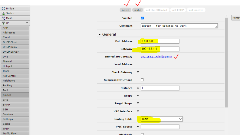
- 1 for the “main” built-in routing table so that e.g. Mikrotik update traffic can also go over the same ether1 interface.
Lets add our WiFi interface routing rule
- The items in yellow is what you must populate.
- The items in red is what Mikrotik will automatically show once you save this routing rule and everything is OK.
A couple of things to note:
- Remember in the beginnig of this tutorial I said my DLink IP address is 192.168.1.1? This has to be our gateway.
- Dst Address 0.0.0.0/0 means all traffic destined to go outside of the router, i.e. internet traffic
- Select the routing table we created in step 4
Now lets add our second routing rule so that Mikrotik updates can still work
- You will do the same thing as above, but now your Routing Table must be “main”, i.e. the built-in routing table
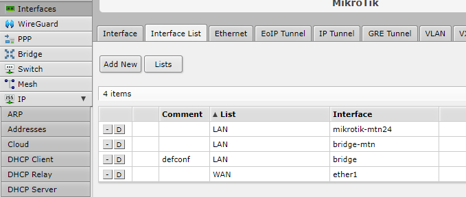
Step 8 – Interface List
One final thing I did that is probably not required for your setup to work it to add the interfaces under LAN.
You will also see that ether1 might be under WAN by default, and that is because there might be a default firewall NAT rule that says to NAT out over the ether1 interface.
If you DO NOT use that NAT rule or the WAN interface, you can disable ether1 — WAN, otherwise leave it alone.