In this tutorial we will look at setting up the Arduino IDE and writing a basic program to flash an LED using the delay function and not using the delay function.
Delay is not the best as the entire ESP32 is asleep and when things like button presses happen during that delay, it won’t register.
We will also look at some other projects like the soil moisture sensor, DHT22 temperature and humidity sensor, etc.
Download the Arduino IDE
Download the Arduino IDE from here: https://www.arduino.cc/en/software
Add the ESP32 board to the Ardiuno IDE
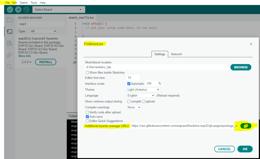
Once the Arduino IDE is installed, go to File, Preferences, and add the below URL:
https://raw.githubusercontent.com/espressif/arduino-esp32/gh-pages/package_esp32_index.json
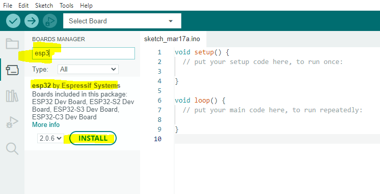
Now go to Tools, Boards, Board Manager and search for and install the ESP32 board:
ESP32 buttons and boot mode
The ESP32 has 2 buttons. The one is labelled EN and the other one BOOT.
- Download mode: Press and hold BOOT while pressing EN. This will put the ESP32 into download mode so that you can push firmware to it (from the Arduino IDE in this case)
- SPI Boot: Press the EN button to restart the ESP32. Especially useful after a firmware flash or to get the ESP32 out of Download Mode.
Remember this so that we can flash a basic program to it shortly. BUT, you typically don’t have to put your board into download mode, the Arduino IDE does it automatically when you deploy code. The only button to really worry about is the EN button when things don’t work as expected after a flash or power cycle.
Configure the Arduino IDE
Now we need to connect our ESP32 to our computer using a USB cable. Windows might install some drivers, let it do its things.
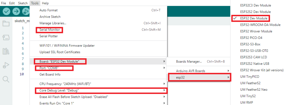
Open the Arduino IDE and select the following:
- Your board (if you are unsure which one you have, select ESP32 Dev Module)
- Select your COM port. Mine is COM 6, yours might be different.
- Make sure your Serial Monitor is active at the bottom of the Arduino IDE
- Set your Debug Level to “Debug” for now.
- We will close this again, its just to see, for now, if there is communication between the IDE and our board.
Press the EN button on your ESP32 that is connected to your computer. The Serial Monitor should output a bunch of stuff. If it does, good. You can disable the Serial Monitor again.
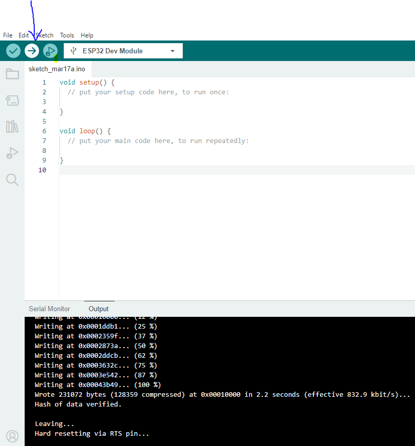
Now click on the Upload button as indicated below. A new window at the bottom of the IDE called “Output” will open showing the firmware upload. We’re all good to write out first basic program.
Our first basic program: Blinking an LED
You will need the following (disconnect the USB cable from your ESP32 first)
- A basic LED
- A 100ohm or 330ohm resistor (or round about there)
- Some jumper wires
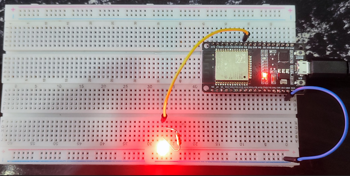
- Connect your ESP32 ground to the blue power rail on your breadboard
- Connect the LED’s flat edge to ground (this is the cathode or the negative PIN)
- Connect the positive PIN of the LED to the resistor which in turn connects to any digital PIN on the ESP 32 (I used D5)
Add the following code to your IDE and click the upload button:
const int ledPin = 5;

void setup() {
  // setup pin 5 as a digital output pin
  pinMode (ledPin, OUTPUT);
}

void loop() {
  digitalWrite (ledPin, HIGH);	// turn on the LED
  delay(1000);	// wait for half a second or 500 milliseconds
  digitalWrite (ledPin, LOW);	// turn off the LED
  delay(1000);	// wait for half a second or 500 milliseconds
}
Check out this guy’s website for more info and great tutorials: https://www.instructables.com/Blinking-an-LED-With-ESP32/
Blinking an LED without delay
#define LED_PIN 5
#define BLINK_INTERVAL 2000 // interval at which to blink LED (milliseconds)

// Variables will change:
int ledState = LOW;
unsigned long previousMillis = 0;   // will store last time LED was updated

void setup() {
  Serial.begin(9600);
  pinMode(LED_PIN, OUTPUT);
}

void loop() {
  // check to see if it's time to blink the LED; that is, if the difference
  // between the current time and last time you blinked the LED is bigger than
  // the interval at which you want to blink the LED.
  unsigned long currentMillis = millis();

  if (currentMillis - previousMillis >= BLINK_INTERVAL) {
    // if the LED is off turn it on and vice-versa:
    ledState = (ledState == LOW) ? HIGH : LOW;

    // set the LED with the ledState of the variable:
    digitalWrite(LED_PIN, ledState);

    // save the last time you blinked the LED
    previousMillis = currentMillis;
  }
}
The code above is rather self explanatory but read the full post if you need more info or want to combine the code below with a button: https://esp32io.com/tutorials/esp32-led-blink-without-delay
Soil moisture sensor
I am using the resistive sensor which is apparently not as good as the capacitive sensor, but it still gets the job done. Here is the code (together with the LED code).
Keep in mind that my soil moisture sensor reads about 3180 when its pins are fully submerged and it will read 4095 when it is completely dry. Yours might be different so play around with it.
#define LED_PIN 5
#define MOISTURE_ANALOG_PIN 32 //my value will range from 3180 (submerged) to 4095 (no moisture)
#define BLINK_INTERVAL 2000 // interval at which to blink LED (milliseconds)

//LED Variables:
int ledState = LOW;

//Moisture sensor variables
int moistureAnalogValue = 0;
int moistureAnalogValuePercent = 0;

unsigned long previousMillis = 0;   // will store last time LED was updated

void setup() {
  Serial.begin(9600);
  pinMode(LED_PIN, OUTPUT);
}

void loop() {
  // check to see if it's time to blink the LED; that is, if the difference
  // between the current time and last time you blinked the LED is bigger than
  // the interval at which you want to blink the LED.
  unsigned long currentMillis = millis();

  if (currentMillis - previousMillis >= BLINK_INTERVAL) {
    //LED related code
    // if the LED is off turn it on and vice-versa:
    ledState = (ledState == LOW) ? HIGH : LOW;
    // set the LED with the ledState of the variable:
    digitalWrite(LED_PIN, ledState);
    // save the last time you blinked the LED

    // Moisture sensor related code
    moistureAnalogValue = analogRead(MOISTURE_ANALOG_PIN);
    // input value, fromLow, fromHigh, toLow, toHigh.
    moistureAnalogValuePercent = map(moistureAnalogValue,3180,4095,100,0);
    Serial.print("Moisture : ");
    Serial.print(moistureAnalogValue);
    Serial.print(" -- ");
    Serial.print(moistureAnalogValuePercent);
    Serial.println("%");

    previousMillis = currentMillis;
  }
}
Check out this page for more detail: http://www.esp32learning.com/code/esp32-and-soil-moisture-sensor-example.php
DHT22 Temperature and Humidity Sensor and sprintf
In this tutorial we will hook up the DHT22 temperature and humidity sensor. I am using the one that is already on a circuit board and contains the relevant resistors and such.
First, lets install the DHT library. Go to Sketch, Include Library, Manage Libraries and install the following library. Install the dependencies as well if it asks.
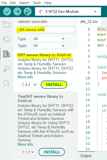
You can open and close your IDE to make sure the libraries are installed properly.
In the code below we are including the DHT.h library and setting the DHT object as the DHT22 sensor type. We are also using sprintf for much less code when priting to the serial monitor.
#include <DHT.h>
#define DHT_SENSOR_PIN 32
#define DHT_SENSOR_TYPE DHT22 //You get DHT11 and DHT22. I am using DHT22
DHT dht_sensor(DHT_SENSOR_PIN, DHT_SENSOR_TYPE); //define the sensor object

#define READ_INTERVAL 5000 // interval at which to blink LED (milliseconds)
unsigned long previousMillis = 0;   // will store last time LED was updated

void setup() {
  Serial.begin(9600);
  dht_sensor.begin(); // initialize the DHT sensor
}

void loop() {

  unsigned long currentMillis = millis();

  if (currentMillis - previousMillis >= READ_INTERVAL) {
    // read humidity
    float humi  = dht_sensor.readHumidity();
    // read temperature in Celsius
    float tempC = dht_sensor.readTemperature();

    // check whether the reading is successful or not
    if ( isnan(tempC) || isnan(humi)) {
      Serial.println("Failed to read from DHT sensor!");
    } else {

      char buffer[100];
      sprintf(buffer, "Humidity: %f % with temperature %f Celcius", humi, tempC);
      Serial.println(buffer);

    }
    previousMillis = currentMillis;
  }
}
Read here for more information: https://lastminuteengineers.com/esp32-dht11-dht22-web-server-tutorial/
ESp32 Ultrasonic Sensor (HC-SR04)
/*********
  Rui Santos
  Complete project details at https://RandomNerdTutorials.com/esp32-hc-sr04-ultrasonic-arduino/

  Permission is hereby granted, free of charge, to any person obtaining a copy
  of this software and associated documentation files.

  The above copyright notice and this permission notice shall be included in all
  copies or substantial portions of the Software.
*********/

const int trigPin = 5;
const int echoPin = 18;

//define sound speed in cm/uS
#define SOUND_SPEED 0.0343

//The duration variable saves the travel time of the ultrasonic waves (time elapsed since transmission and reception of the pulse wave)
long duration;
float distanceCm;

void setup() {
  Serial.begin(9600); // Starts the serial communication
  pinMode(trigPin, OUTPUT); // Sets the trigPin as an Output
  pinMode(echoPin, INPUT); // Sets the echoPin as an Input
}

void loop() {
  // Clears the trigPin In the loop(), the following lines produce a 10uS HIGH pulse on the trigger pin—this means the pin will emit an ultrasound.
  // Note that before sending the pulse, we give a short LOW pulse to ensure you’ll get a clean HIGH pulse.
  digitalWrite(trigPin, LOW);
  delayMicroseconds(2);
  // Sets the trigPin on HIGH state for 10 micro seconds
  digitalWrite(trigPin, HIGH);
  delayMicroseconds(10);
  digitalWrite(trigPin, LOW);

  // Reads the echoPin, returns the sound wave travel time in microseconds
  // We use the pulseIn() function to get the sound wave travel time
  // The pulseIn() function reads a HIGH or a LOW pulse on a pin. It accepts as arguments the pin and the state of the pulse (either HIGH or LOW). It returns the length of the pulse in microseconds.
  // The pulse length corresponds to the time it took to travel to the object plus the time traveled on the way back.
  duration = pulseIn(echoPin, HIGH);

  // Calculate the distance
  distanceCm = duration * SOUND_SPEED/2;

  // Prints the distance in the Serial Monitor
  Serial.print("Distance (cm): ");
  Serial.println(distanceCm);


  delay(1000);
}
For a full write up on how the code works check out this link: https://randomnerdtutorials.com/esp32-hc-sr04-ultrasonic-arduino/
For great tutorials, check out these sites:
https://esp32io.com/tutorials/esp32-button
https://www.tme.eu/Document/31b16b9b46c633740aeab1a29cd0f7fd/esp32-devkit.pdf
https://randomnerdtutorials.com/esp32-hc-sr04-ultrasonic-arduino/